D Latch Circuit Characteristic Table
Digital Circuits Latches Tutorialspoint
Latches In Digital Logic Geeksforgeeks

Digital Circuits Latches Wikibooks Open Books For An Open World
D Flip Flop Or D Latch What Is It Truth Table Timing Diagram Electrical4u

Digital Circuits Flip Flops Tutorialspoint

D Type Flip Flop Counter Or Delay Flip Flop

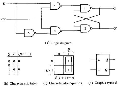
The following table shows the state table of d latch.
D latch circuit characteristic table. That means the output of d latch is sensitive to the changes in the input d as long as the enable is high. Latch is an electronic logic circuit with two stable states i e. Thus the output has two stable states based on the inputs which have been discussed below. There are many applications where separate s and r inputs not required.
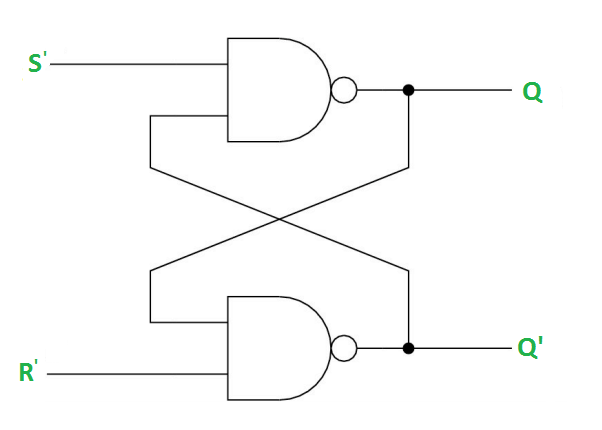
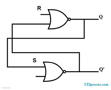
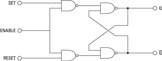
Hence a latch can be a memory device. Sr latches a sequential circuit that has two inputs set that sets the latch and reset that clears the latch and two complementary outputs. In this chapter we implemented various latches by providing the cross coupling between nor gates. Latch can store one bit of information as long as the device is powered on.
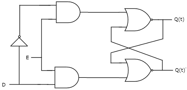
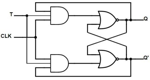
S r nor latch s r nand latch 4 1. D latch can be gated and then the logic circuit can be as follows gated d latch. For this reason d latch is sometimes called a transparent latch. In this situation the latch is said to be open and the path from the input d to the output q is transparent.
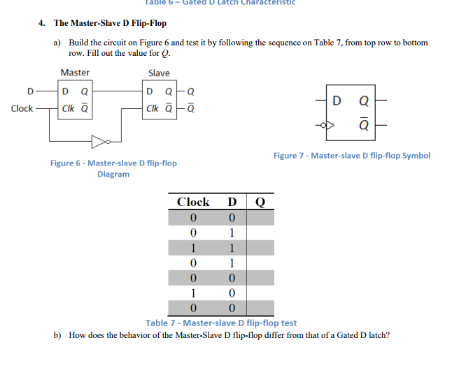
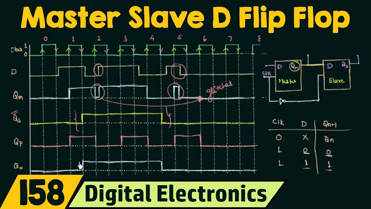
Thus d flip flop is a controlled bi stable latch where the clock signal is the control signal. When e is 0 the latch is disabled or closed and the q output retains its last value independent of the d input. In these cases by creating d flip flop we can omit the conditions where s r 0 and s r 1. Q n 1 en d en q n.
When enable is asserted latch immediately. Thus the circuit is also known as a transparent latch. Looking at the truth table for d latch with enable input and simplifying q n 1 function by k map we get the characteristic equation for d latch with enable input as. Unlike the combinational circuits the outputs of the latch are not uniquely determined by the current inputs.
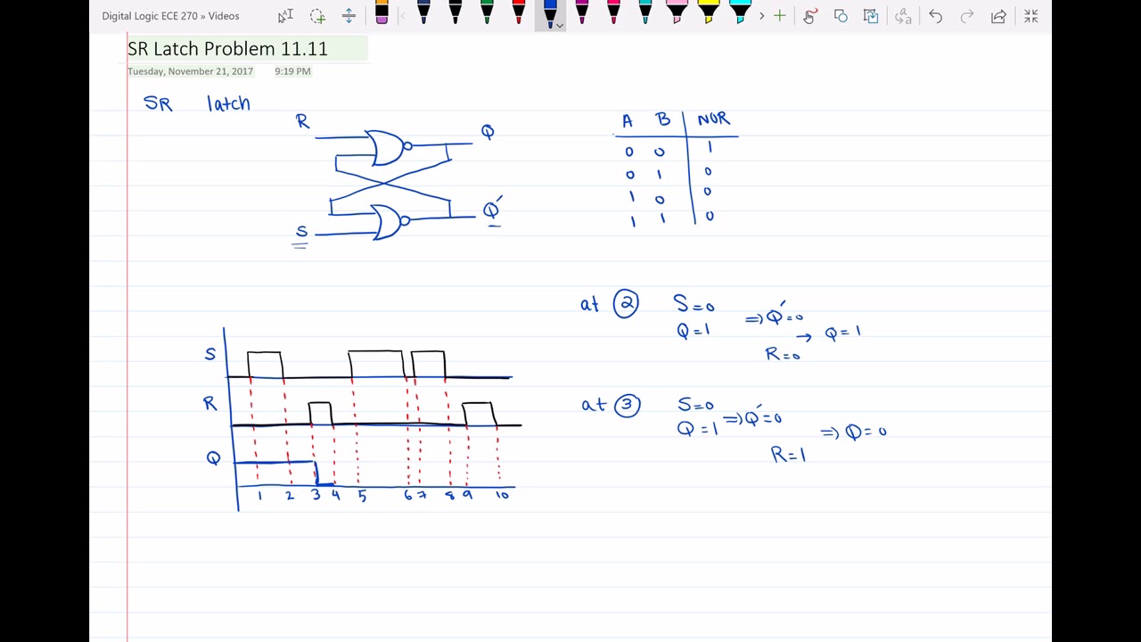
It is a bistable multivibrator. Characteristic tables s r q n 1 0 0 q n 0 1 00 1 0 11. Again this gets divided into positive edge triggered d flip flop and negative edge triggered d flip flop. As shown in the truth table the q output follows the d input.
Latch has a feedback path to retain the information. Truth table characteristic table and excitation table for d flip flop contribute. So when the device is disabled e 0 it holds its current value and when enabled e 1 it can be set or reset i e. Truth tables characteristic equations and excitation tables of different flipflops nand and nor gate using cmos technology circuit design of a 4 bit binary counter using d flip flops.
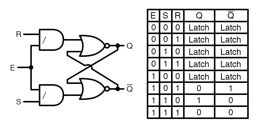
A circuit implementation of the gated d latch is shown in figure 60.
Flip Flop Truth Table Various Types Basics For Beginners

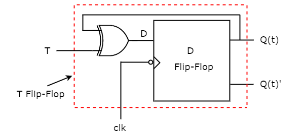
Designing Of T Flip Flop
Latches Types Advantages Disadvantages And Their Applications
Solved I Need To Build The Following Circuit Of A Master Chegg Com

Circuit Configuration Of The Cml Type Sr Latch Circuit A Circuit Download Scientific Diagram

Truth Table Characteristic Table And Excitation Table For Sr Flip Flop Youtube
Sr Latch Timing Diagram Youtube

Wy 8775 Circuit Diagram D Latch Wiring Diagram
Electronics Basics What Is A Gated Latch Dummies

Https Encrypted Tbn0 Gstatic Com Images Q Tbn 3aand9gcqg1mtgrnmr84ikfy13wdrbnh4 B7xnzjjypq Usqp Cau
Digital Circuits Conversion Of Flip Flops Tutorialspoint
Sr Flip Flops
Nand Gate S R Enabled Latch Digital Integrated Circuits Electronics Textbook
Circuit For Toggle Flip Flop Using Cd4013 Circuit Diagram Electronics Circuit Circuit
Introduction To D Flip Flop Youtube

Solved Use The Finite State Machine Fsm Methods To Desi Chegg Com
Homework 5 With Solutions Homework Eecs 31 Cse 31 Ics 151 Daniel D Gajski S Web Site

State Tables And State Diagrams
Https Encrypted Tbn0 Gstatic Com Images Q Tbn 3aand9gcseowu7grcyaqix7uy V0eiectmzfp 83opypjy5v Aeixppjq5 Usqp Cau

Schematic Circuit Diagram For 6 Input Mixer Simple Schematic Collection In 2020 Circuit Diagram Circuit Mixer
Flip Flop Circuits Worksheet Digital Circuits

Know All About Latches And Flip Flops
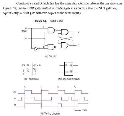
Construct A Gated D Latch That Has The Same Charac Chegg Com